Table of Contents
- Introduction
- Assemble the Parts
- Configure the Radio
- Wire up the Circuit
- Use it!
1) Introduction
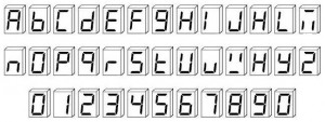
Number communicate clearly. With a simple 7-segment numeric display you can show how many, how much, which one or when with precision. It's a snap to display numbers wirelessly with an Digi XBee radio. The Digi XBee directly drives a simple numeric display, and that's often all a project needs. For example, here's some characters you can show in seven segments, (click the image to see even more possibilities ):
The numbers can be small or huge. For applications that require extensive text, check out our LCD text display example for rich communications. Otherwise when simple numbers and letters fit the bill, here's how to get 'em....
2) Assemble the Parts

To hook up a 7-segment numeric display to an XBee, you'll need:
4) Wire up the Circuit
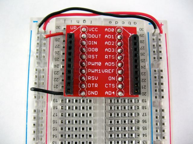
Place the Digi XBee adapter into the breadboard and wire up the power buses to each other. Next, connect the VCC terminal of the XBee adapter to the positive rail and the ground terminal to the negative rail.
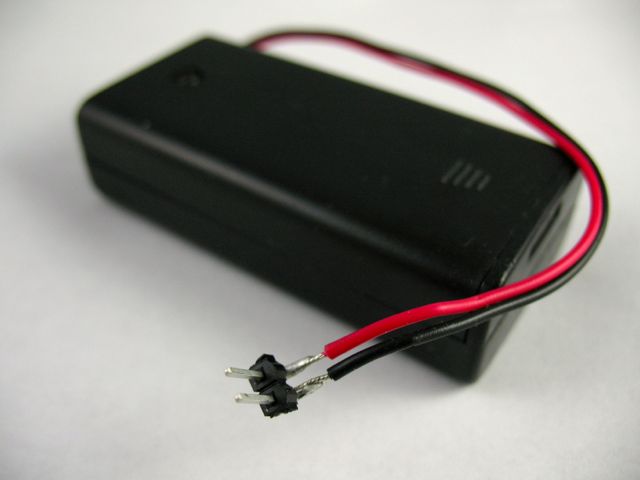
We made it easier to attach the battery holder to the breadboard by soldering some male headers onto its positive and negative wiring leads.
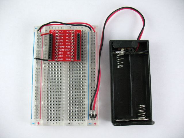
Connect the battery pack directly to the ground and power rails.
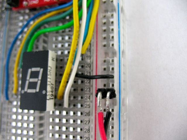
Place the 7-segment display module across the trough in the breadboard as show, so that the two columns of pins go into separate breadboard rows. The display shown is a common-cathode model which means that all the LED segments share a command ground connecting. Attach one or both of the GND pins to the ground rail of the breadboard. For this module we use physical pin 12. You can either use a regular wire or a low-value resistor (~100 Ohm) to make the connection.
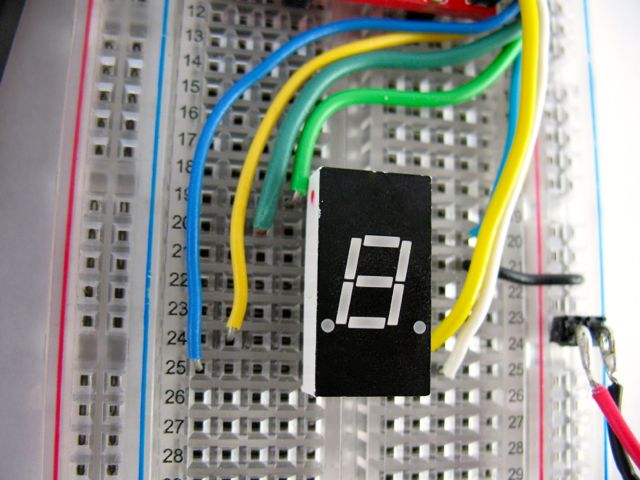
The remaining pins each run one segment of the numeric display.

Wire each one to a digital output on the XBee.
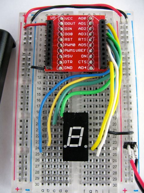
Here's the connections for the 7-segment display that we used (great data sheet notes here). Yours may be different so check its data sheet and connect it accordingly!
| XBee pin |
XBee physical |
Display pin |
Display physical |
| AD0 |
20 |
segment A |
14 |
| AD1 |
19 |
segment B |
13 |
| AD2 |
18 |
segment F |
1 |
| AD3 |
17 |
segment G |
2 |
| AD4 |
11 |
segment E |
6 |
| AD5 |
15 |
segment D |
7 |
| AD6 (RTS) |
16 |
segment C |
8 |
| AD7 (CTS) |
12 |
segment RDP |
9 |
| n/a |
[GND] |
common cathode |
4 |
| n/a |
[GND] |
common cathode |
12 |
Note: The particular organization of the segments can be changed according to your taste.
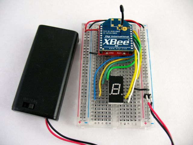
And finally, insert the Digi XBee into the breakout board and connect the battery pack. If there's a switch on the battery pack be sure to switch it to the on position. All the segments should be off to start with. Now any pins brought high on the Digi XBee, either remotely or from the Internet via XIG will turn on one of the segments. For example, to show the decimal number 5, turn on segments A, F, G, C and D! See Setting or Getting Remote Digi XBee AT Settings on the XIG for more information on remotely setting pins via iDigi.
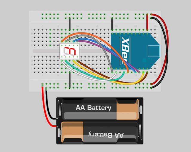
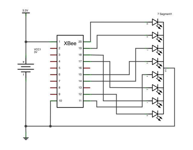
Above is a breadboard layout and a diagram of the circuit for your reference.
5) Use it!
For this video we got those numerals pouring out of the Digi XBee by using the Remote Digi XBee AT Settings feature of the XBee Internet Gateway. It's an easy way to switch the LED segments on and off from the Internet. You could also use the Arduino XBee Library to run a local display wirelessly. Now you can create a counter that shows how far away Friday is, display your current Amazon or Yelp ratings, show the current flight landing at O'Hare or keep an eye on the temperature in your restaurant's walk-in freezer. A 7-segment display can keep you, your employees, and your customers in the know!