This XBee Tech Tip is brought to you by Digi Applications Engineer Mark Grierson.
When working with
Digi XBee RF modules, you can use API mode to send commands from a transmitting radio to a receiving radio. This allows for module parameter registers on a remote device to be queried or set. One useful application of this feature is to toggle an IO on a remote radio from a high to a low state. In this manner the radios can be used as a wireless relay to control a wide variety of remote devices.
Overview: Sending API Frames
In this tutorial we will be using
Digi XCTU® to create and send 2 distinct API frames. One frame will toggle the remote radios
IO high, and the other will toggle the remote radios
IO low. You could easily program a micro or other piece of hardware to issue these commands.
Setup
To perform this tutorial you will require the following materials:
- 2 - XBee 802.15.4 RF modules.
- 2 - Interface boards (USB or RS-232)
- Note that the use of DEV boards (XBIB-U-DEV or XBIB-R-DEV) will allow the use of onboard LEDs to observe output
- 1 - PC with XCTU software installed. Click here to download XCTU.
- Serial or USB cables to connect interface boards to the PC
Procedure
Select one radio to operate as your Base and one to operate as your Remote. Both radios are programmed with the default settings with the following exceptions. API is enabled on the Base radio (AP=1), D4=4 on the remote radio.
In this example my radios have the following factory set 64 bit addresses:
Base:
- SH=0013A200
- SL=403199EB
- AP=1
Remote:
- SH=0013A200
- SL=4055F498
- D4=4
Steps:
1. Connect the base radio to the PC and launch XCTU.
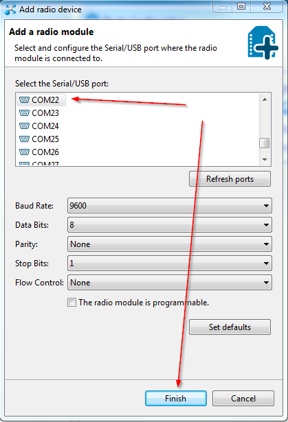
2. Connect the radio to XCTU by clicking on the
Add Devices icon and selecting the appropriate com port and settings and clicking finish.
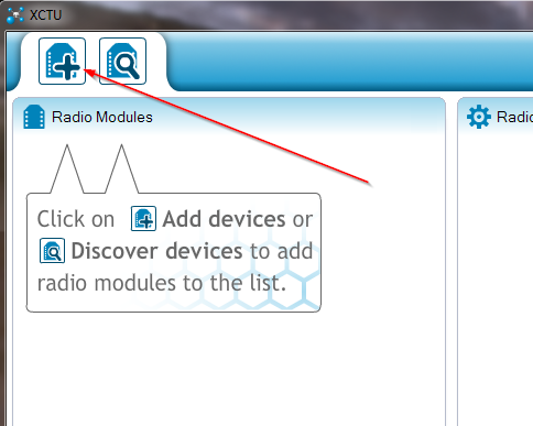
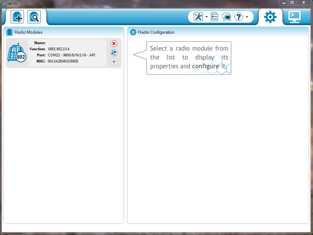
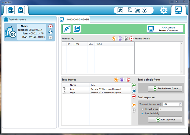
The radio will now be listed on the left side of XCTU as in the following screenshot.
3. Open the Console mode of XCTU by clicking on the Console icon.

4. Open the serial connection with the base radio by selecting the Connect icon.

The image will change to the connected status.

The Console should indicate that it is opn as an API Console.

If it is showing that it is an AT console, return to the module settings tab and ensure API is enabled (AP=1)
5. In the Send a single frame section open the "Add a frame" dialog box by clicking on the

.
6. Rename your frame name to Low, then click on the Packet generator icon

to open the packet generator.
We will now use the built-in API frames generator to create two remote AT command (type 0x17) frames paying close attention to the structure of this frame as outlined in the API section of the Product manual. One frame will set the remote radios digital output
high and the other will set it
low.
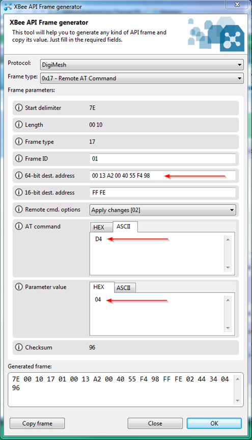
7. Select "0x17 - Remote AT Command" as the frame type and then set the 64 bit address to the SH and SL of the remote module. Set the AT command to ASCII D4 and the Parameter value to HEX 04 as in the following screenshot.
*Please note that the command D4 (bytes 17 and 18) is issued as 44 and 34. 34 is the hex equivalent of the ASCII character 4. The parameter value setting for D4 (byte 19) is issued as 04 and 05. This is the hex equivalent of decimal 4 and 5 respectively.
8. Click
OK and the frame contents will appear in the Add API frame to the list dialog box as follows:

9. Click
Add frame.
10. Repeat the procedure for your set high frame, changing the parameter value to 0x05 and create a second frame with a frame name of
high.

11. Click
Add frame.
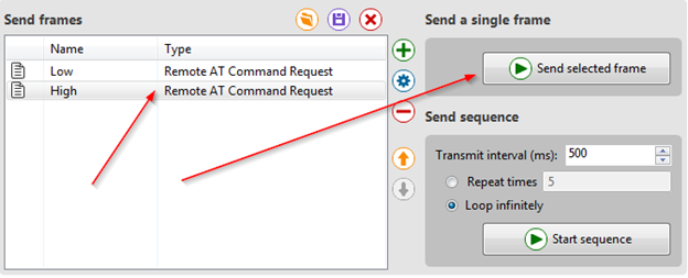
Your API console should now look something like this:
Here are the frames configured for the address of my radios. Your packets will contain the address of your remote radio and the checksum will be different.
Note: I have chosen to toggle DIO4 as it is connected to LED 3 on the XBIB-DEV board and allows easy viewing of the toggle process without the use of a voltmeter or scope.
Command to set DIO4 high:
7E 00 10 17 01 00 13 A2 00 40 55 F4 98 FF FE 02 44 34 05 95
Command to set DIO4 Low:
7E 00 10 17 01 00 13 A2 00 40 55 F4 98 FF FE 02 44 34 04 96
12. You can now send the commands to the base radio which will in turn send remote commands to the remote radio to set its digital output D4 (Pin 11). Do this by highlighting the appropriate frame (high or low) and clicking
Send selected frame.
The LED associated with the D4 pin should go off and on as you send these two frames. You may also verify the state by connecting a multi-meter to Pin 11 of the module to check its voltage state as it is toggled from high to low. The pin should read about 3.3v when high and about 0 volts when low.
You can also view and parse the frames and their corresponding response packets in the Frame log section of the display. A status of 0x00 (OK) indicates that the frame was sent successfully and acknowledged by the remote module.
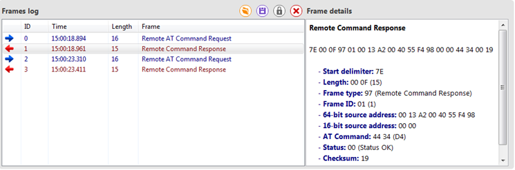
If you do not receive a response frame, be sure to check your API packet for accuracy.
Note: This article is written using the XBee 802.15.4 radios but the concepts are applicable to all of the XBee radio lineup that offer API mode.